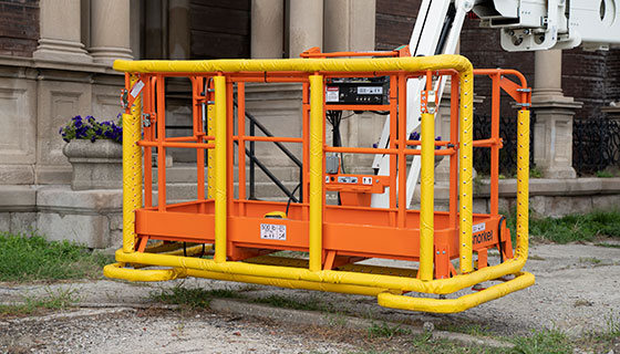

The Snorkel Aircraft Bumpguard System provides all-around protection on a jobsite. This safety feature equips boom and scissor lifts with a pressure-sensitive switch designed to prevent damage to the unit or object from unintended impact. This factory installed option stops platform movement when the platform comes in contact with a stationary object.
Although the system was first designed for aircraft applications, it may also be used at other jobsites where work surface contact may result in costly repairs, such as glass clad buildings, delicate instrument installations, etc.
The Snorkel Aircraft Package and Deluxe Aircraft Package accessories, which include the Snorkel Aircraft Bumpguard System, are available on a wide range of Snorkel boom lifts including the 400S/460SJ and 600S/660SJ telescopic boom lifts; A46JE electric articulating boom lift; and A46JRT, AB60J, AB80J and AB85J diesel articulating boom lifts.
Designed to provide protection against damage when working on or around aircraft, the Aircraft Package will shut off machine operations if contact is made to the platform. This option also includes an easy access swing gate and a tow kit for use around the airport.
The Deluxe Aircraft Package includes all the features of the Aircraft Package plus an enhanced padded bumpguard. This package features a rubberized liner within the bumpguard for added safety with front-mounted tow kit for easy transportation and fall arrest protection.
Aircraft Bumpguard System Features
The Snorkel Aircraft Bumpguard System features for boom lifts includes:
- Foam padded platform rails
- Spring suspended rail under the platform
- Photoelectric switches to stop all platform movement upon stationary object contact
- Override control to regain full control of platform movement
Operation
The Snorkel Bumpguard System consists of a padded, spring-suspended frame located under and around the bottom of the platform that is activated only when the booms are extended or elevated past the limit switches.
The system is equipped with a pair of infrared photoelectric switches to sense frame movement. These switches are mounted on the platform and project an infrared light beam onto a “target” mounted on the frame. The beam is then reflected back to the switch to indicate the normal position.
If the suspended frame comes in contact with a stationary object, the movement (about ¾ in. or 19mm) breaks the reflected light beam, and the photoelectric switch signals a relay to interrupt power to all function controls at the platform, bringing all movement to a halt.
The operator must engage the override switch on the upper control panel to move the unit while the infrared switch is off its target. When the override procedure moves the platform away from the object, the spring-loaded frame realigns the target with the light beam on the switch. This restores the normal operating circuit and disables the override circuit.
A clear plastic lens with a green or red indicator light is located on the end of the switch. These lights are used to indicate the operation of the switch and set the sensitivity on the sensor.
- Green light: Indicates that the beam is on target
- Red light: Indicates that the beam is marginally on the target
- No lights: Indicates that the beam is off target and the cutout is activated
Inspection
Before beginning the inspection procedure, be sure that the target and photocell lenses are clean. Do not use abrasives or strong solvents for cleaning.
Use the following procedure to inspect the Snorkel Bumpguard System on boom lifts:
- Activate the system by raising or extending the main boom beyond either limit switch. The Emergency Stop switch and the platform footswitch must be activated.
- Check the photocell operation by moving the frame so that a target is no longer under one of the photocells. The lights should turn off. The green lights should turn back on and remain on when the frame is released.
- Lift the frame so that the targets move directly towards the photocell. The lights should turn off when the frame is lifted ½″ to ¾″.
- Adjustment is necessary if the system does not operate as indicated in Steps 2 and 3.
The optional Aircraft Package and Deluxe Aircraft Package on Snorkel boom lifts available at https://www.snorkellifts.com/equipment/category/Accessory-Packages.